Hotline  +48 34 39 30 015 or +48 601 913 288
  sklep@termipol.pl

 Exists
 Payment on delivery, Traditional Bank Transfer (Pro forma), Fast online payments
The product is shipped within 24 hours.
We complete the order within 24 hours.
The product is covered by a one-year warranty.
You can return the product within 14 days.
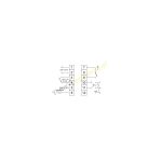
| Power supply: | 185-230 VAC |
| Regulation: | On/Off, PID |
| Output: | Relay, Voltage (SSR) |
| Max. Load: | 3 A |
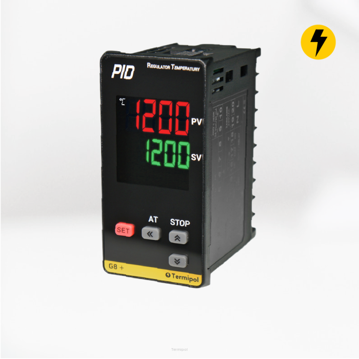
| Display: | PV (Present Value), SV (Set Value) |
| Sensor Service: | B, E, J, K, PT100, S, T |
| Emergency Exit: | AL2 przekaźnikowe (3A) |
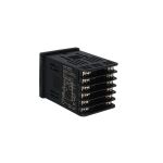
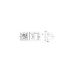
| Dimension: | 48x48 mm |
| Resolution: | 0,1°C |
![]()
Compact and precise controller for demanding users. The characteristic feature is high measurement accuracy. An additional advantage is the possibility of controlling both an SSR relay and a normal relay.


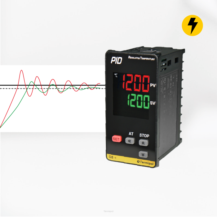
| PID is an internal algorithm stored in the memory of the control device. It can be treated as an additional function that improves control and control because it adapts to the system in which it is installed. Without automatic regulators, all regulation tasks had to be done manually by people! |


PID regulation is used for precise temperature control without hysteresis (deviation). Control is carried out here by pulsed activation of the control output, in this case it is worth using solid state relays SSR (Solid State Relay), which are not sensitive to frequent switching on.
| More information on our blog: What is PID? |

The regulator has an auto-tuning function, which is activated only once after the regulator is installed in the machine or furnace. It consists in the fact that the regulator automatically selects PID values in order to maintain the set temperature as optimally and accurately as possible. The PID parameters can also be changed manually. The regulator can maintain the temperature on the extruder with an accuracy of 0.1°C.
| More information on our blog: Selection of PID settings in practice. |
When using the standby function, it prevents the output alarm (ON) set in LOW mode from being triggered from the time the regulator is turned on until the set temperature is reached.
If the output LOCK option is selected for the Alarm, it is not cleared even if the boundary conditions of this alarm are met. To clear the alarm with the LOCK option, press and hold the "up arrow" key for 2s. Example: If we set a temperature of 100 C for AL1 and set the "alarm 1 output LOCK - ON" option, then when this value is exceeded, AL1 will be triggered and will be maintained even if the temperature drops to, for example, 75 °C.
Once 0% or 100% of the set value in PID mode is reached, the time measurement begins. Additionally, this feature allows for fault detection of the heater or sensor by monitoring the speed of the changes in the measured value in the period set in the Loop Break Alarm Time parameter. Additionally, it is possible to set the dead zone for the LBA alarm (Loop break alarm dead zone).
If 100% of the set value in PID mode is reached, and the temperature rises above the value declared in the parameter "Loop Break Alarm Temperature" within the time specified by the parameter "Loop Break Alarm Time", then the LBA 2 alarm will be triggered. If 0% of the set value in PID mode is reached, and the temperature drops below the value declared in the parameter "Loop Break Alarm Temperature" within the time specified by the parameter "Loop Break Alarm Time", then the LBA alarm will be triggered.
The control cycle is coupled with the supply voltage frequency. For this mode of operation, it is recommended to use RANDOM ON/OFF SSR relays (recommended for inductive loads, where delays resulting from the use of ZERO-CROSSING relays may cause incorrect device operation).
The controller controls the relay cyclically, adjusting the actuation time during the control cycle determined by the user using the Ct parameter. The most popular mode of operation for typically resistive loads (heating elements or other with low impedance).